Opening up the DEC Precision Display 340
This system has 0 sponsors yielding $0.00/mo in support.
Simulating a P7 point-drawing CRT is hard; the behavior of the phosphor is subtle and distinctive, and the optics of seeing the image painted on an actual period correct CRT are awesome.
The ICM has the DEC 340 cabinetry and the CRT, but most of the logic is missing. Replacing the missing circuitry is a work-in-progress; the analog circuitry to drive the deflection coils and the beam intensity have replaced with re-implementations of the original logic.
However, the digital side has not yet been done.
The PDP-6 that the 340 is attached to is in similar shape, the cabinetry and panels are intact or replaced, but the insides are gone and have been replaced with a Pi.
Because the -6 is being simulated on a Pi, there is no need to replace the 340 I/O bus circuitry; that can be simulated on the Pi, and it can send the X/Y point coordinates and control signals out a GPIO port.
So the remaining bits that are needed for the 340 are two GPIO driven DACs generate -10 to 0 volt outputs based on +/- 1024 coordinate values, and figuring out how to wire the DAC outputs into the existing analog circuits.
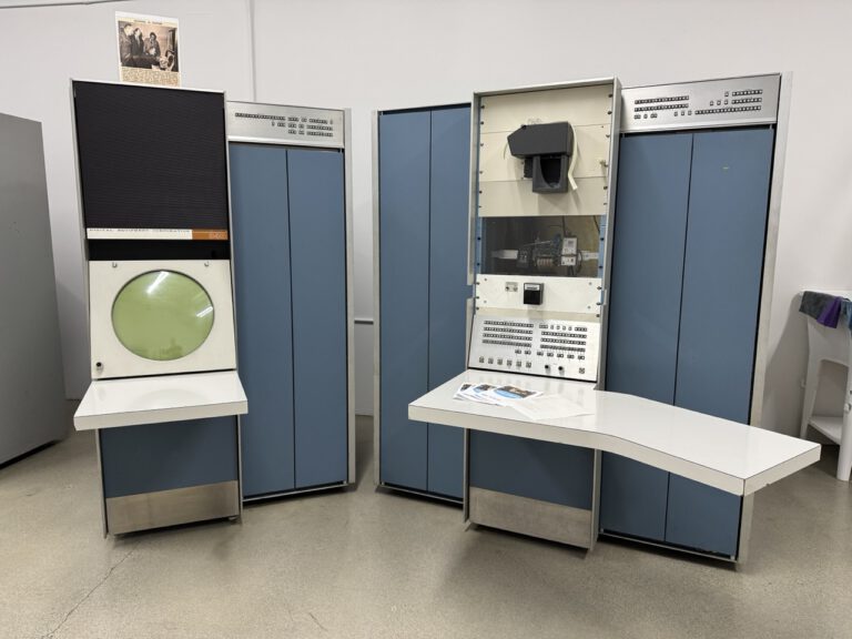
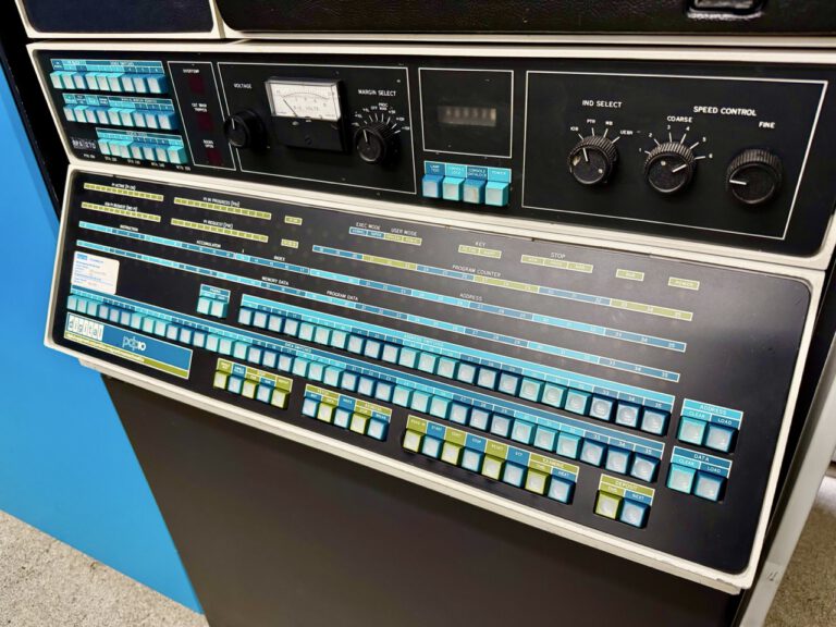
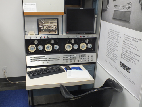
The PDP-6
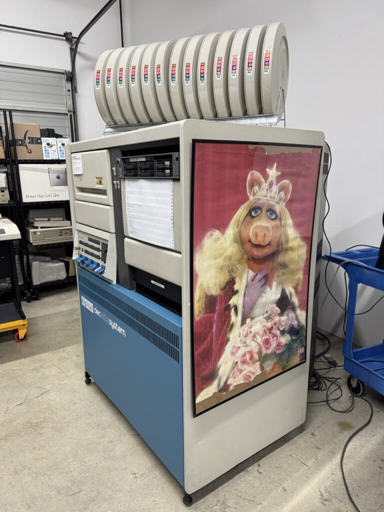
The Display 340
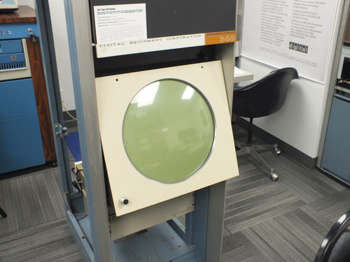
The insides of the 340
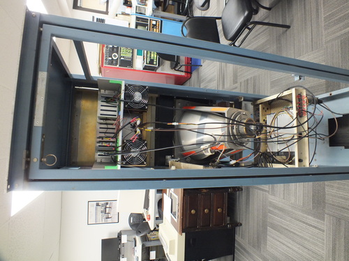
The top row contains the beam focus and bias card, two deflection pre-amplifiers (vertical and horizontal) and two unpopulated cards which I believe to be intended as Digital to Analog cards to drive the pre-amplifiers.
The second row (with the fans) are the deflection amplifiers.
Below that is the CRT, and below that the logic power supply. Below that but not visible is the high voltage supply for the CRT.
The top row cards are based on the original cards, but some unobtainium components have been replaced, and some of the circuitry has been redesigned to accommodate that. This means that the original circuit diagrams don’t always match what I am seeing on the cards, and the card connector numbering is completely unrelated.
This has made figuring out how to send coordinate data into the pre-amplifiers an uphill slog.
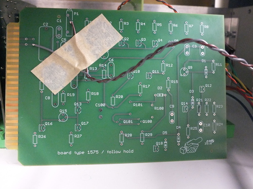
I spent the morning tracing out circuits on the pre-amplifier cards and am reasonably certain that I have located the correct data in line; this turns out to be likely correct as tracing the backplane wiring for the proposed line leads eventually to two pairs of wires that are tacked onto the unpopulated cards; the pairs are several feet long and are not attached to anything, suggesting that they are there to allow test data from a signal generator to be injected.
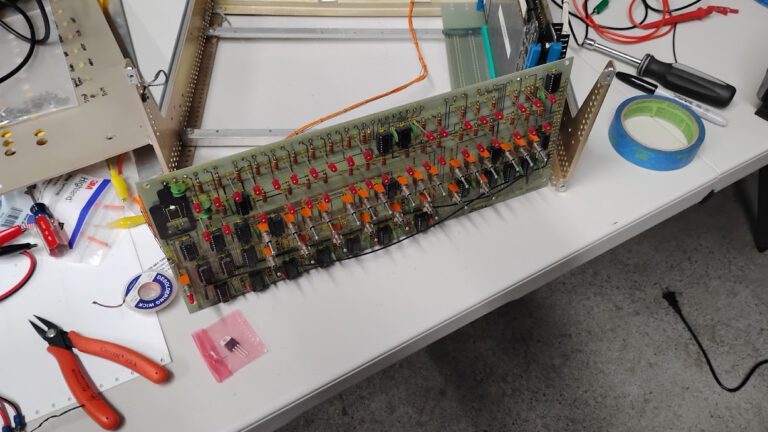
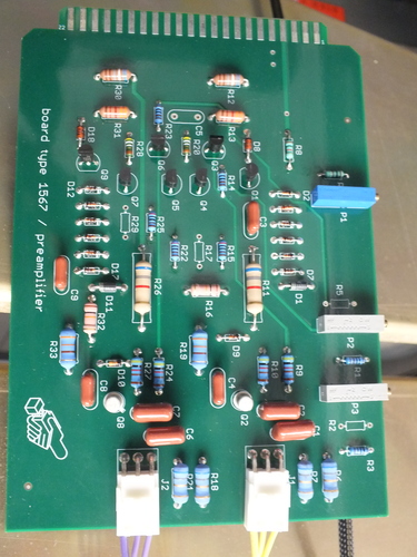
The pre-amplifier card
The card with the interesting wires
Next up, disconnect all of the high voltage bits, attach some meters to the CRT deflection coils, and apply signals to the wires to see if they really are deflection inputs.
Opening up the DEC Precision Display 340, part 2
I initially thought that the DEC Type 30E amd Type 340 Displays were functionally equivalent but with different form factors (Desktop and Rack mount), and I was using the available 30E documentation to understand the innards of the machine. However, it turns out they are quite a bit different as I discovered when I located documentation for the Type 340. And it turns out that what I was seeing inside the 340 made a lot more sense when I used the correct documentation.
Armed with that, I decided I wanted to set up a test that would allow me to set the X and Y coordinates of the dot on the display; it I could get that to work, I would be able to design and build an adapter that would let me move the dot around under the control of a microprocessor.
For this test, I didn’t actually turn the CRT tube; I don’t want to risk burning a hole in the phosphor screen while I fumble around; instead I set up a voltmeter on one of the deflection coils; the voltage there moves the dot left or right (or up and down depending on which coil). I also hooked up a variable power supply to the deflection pre-amplifier input. That input is documented as 0 volts setting the dot to the left side of the screen and -10 volts to the right side. So as I adjusted the voltage to the pre-amplifier, I should observe proportional changes to the voltage on the deflection coil.
Without power applied to the pre-amplifier, the deflection coil showed about 48 volts, which is a reasonable value for deflecting the dot to the right edge. Applying power to the pre-amplifier, I saw the deflection voltage vary by just a few volts, rather the the expect drop to zero volts.
So there is something going on that I do not understand. Next up is to try to locate some missing documentation about the earlier restoration process, and to closely examine the existing reworked hardware to try to understand why I am not getting the expected results. (Specifically I need to trace out the circuit boards to better understand their functionality.)
Opening up the DEC Precision Display 340, part 3
I discussed the deflection circuitry with an actual EE and we decided that the circuitry was actually working; my test procedures were flawed.
So I moved on to the beam intensity circuitry. I know that the first attempt to test that circuitry led to arcing, and that some rework had been done on the board. The drawings included a definition of the D/A behavior and so I powered up that board, but left the high voltage disconnected. I applied the digital signals as defined in the drawings and measured the cathode voltages; the results I saw did not begin to match the documented behavior.
I have come to the conclusion the the intensity control was a work-in-progress, and I will need to get a real EE to get any traction; I am setting the project aside for the nonce.